
- Intelligent Detection SolutionOur solutions help you manage every step of the packaging process, from checking the accuracy of package weight and contents to detecting unwanted substances such as metal and glass mixed in with the product.
 Get Technical Support
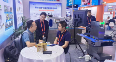
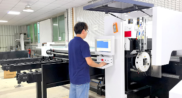
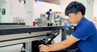


SameGram Installation & Commissioning Services
Engineered for Accuracy. Verified in Your Line.
A dynamic checkweigher only delivers true value when it is correctly installed, calibrated against traceable standards, and validated on your actual production line. From site preparation and mechanical assembly to calibration, line integration, and acceptance testing—ensure that your equipment delivers precise weighing, reliable rejection, and stable operation from the very first shift it enters service.
16years of field experience
5,000+customers served worldwide
12 monthswarranty, lifetime maintenance
How We Work
Our Commissioning Service Models
Three engagement models, one engineering standard. All three conclude with the same acceptance criteria defined in Section 7 of this page — the standard does not change with the service model.
Model A
Full On-Site Commissioning
Complete unpacking, assembly, installation, calibration, integration, and acceptance testing by a SameGram field engineer.
Model B
Supervised Self-Installation
Detailed installation documents, video guidance, and step-by-step remote supervision of your own maintenance team.
Model C
Remote Commissioning Support
Real-time video assistance, parameter configuration, and troubleshooting while your team performs the installation.
Section 1 · Before the Machine Arrives
Pre-Installation Preparation
Commissioning quality is determined before the machine arrives. Verify the items below at least one week before the scheduled installation date so that site, utilities, and personnel are ready on day one. Preparation typically takes 1–2 working days and can run in parallel with inbound logistics.
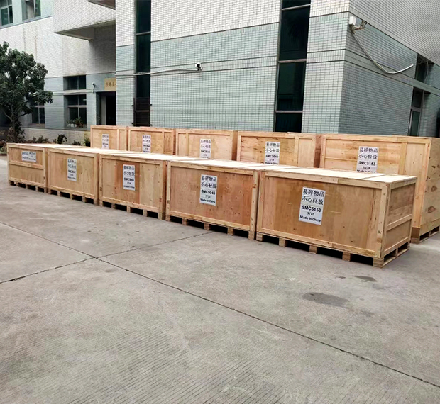 Factory crating and pre-shipment inspection at the SameGram plant
Delivery Inspection & Unpacking
1
Inspect crates before signing
Check every crate for shipping damage (crush, punctures, tilt/shock indicators) beforesigning the carrier's delivery receipt.
2
Document any damage the same day
Photograph and note damage on the delivery document; notify SameGram and the carrier immediately — concealed-damage claims have short legal windows.
3
Unpack in the marked footprint
Unpack at the machine position; verify the packing list against delivered contents (machine, reject unit, HMI, tool kit, documents, spare parts).
4
Report discrepancies first
Report any shortage before assembly begins — packing-list verification is the baseline for the warranty record.
| Site Readiness Item | Requirement |
|---|---|
| Location & layout | Position per the approved layout drawing; product flow direction matches the line (standard: left-in, right-out when facing the machine) |
| Floor & foundation | Level, rigid industrial floor; compensate unevenness with the machine leveling feet — never shim under the load cell |
| Service access | Minimum 800 mm clear space on the operator and maintenance sides (confirm model-specific dimensions on the layout drawing) |
| Environment | Typical operating envelope: 0–40 °C, ≤90 % RH non-condensing, low dust and vibration; washdown-duty variants apply their IP rating |
| Adjacent equipment | Verify conveyor centerline heights and transfer gaps with upstream/downstream equipment before positioning |
| Utility | Specification to Prepare |
|---|---|
| Power supply | AC 220 V ±10 %, 50/60 Hz, dedicated circuit with protective earth (PE), lockable disconnect upstream of the machine |
| Compressed air | Clean, dry, oil-free instrument air (per ISO 8573-1); working pressure 0.5–0.8 MPa; Φ8 mm connection interface |
| Data network | Ethernet port for remote support and data export (recommended) |
| Certified test weights | OIML M1 class or equivalent, covering approximately 20 %–100 % of the machine weighing capacity |
Tools & Lifting Equipment
- Forklift or pallet jack rated for the crated machine weight
- Torque wrench covering the fastener sizes on the installation drawing
- Multimeter, hex key set, adjustable wrench, alignment straightedge
- Pressure gauge for air-line verification and PPE per Section 6
People & Documentation
- One installation supervisor (mechanical), one qualified electrician, one line operator;
- On site: approved layout drawing, installation drawing with fastener torque values, electrical and pneumatic schematics, packing list, and the model data sheet
Section 2 · Mechanical Build
Core Components & Installation Steps
A SameGram checkweigher is a modular machine: frame, weighing conveyor, controller, and reject mechanism install in sequence, followed by electrical and pneumatic connection, then optional process modules.
| Component | Function | Typical Configuration |
|---|---|---|
| Weighing conveyor module | Carries and weighs product in motion | Frame with removable belt; PU food-grade belt; bearings |
| Weighing platform & load cell | Converts load into an electrical signal | Mettler Toledo load cell; free-suspension mounting |
| Controller & HMI | Recipe management, monitoring, operation | 10-inch color touchscreen running the SameGram online weighing control system; stores up to 100 product formulas |
| Reject mechanism | Removes out-of-tolerance product | Push-rod, swing-arm, or top-lift type per order configuration |
| Frame & leveling feet | Structure and alignment | Carbon steel with spray-painted finish (SUS304 stainless variants for hygienic duty) |
| Alarm system | Operator notification | Sound-and-light alarm with automatic rejection |
| Power & control | Supply and drives | Meanwell power supply; drive motors; junction box |
| Optional modules | Process extension | Inkjet coder, real-time printer, labeler, barcode/code reader, sorter, metal detector |
Accuracy note
The weighing platform must be loaded only through the load cell. Any second load path — a cable, chute, belt, or fastener — steals load from the sensor and creates non-reproducible weight error.
Mechanical Assembly — Step by Step
1
Position the main frame
Move the machine to the marked footprint using a forklift or pallet jack rated for the crated weight. Remove shipping restraints and transit bolts. Retain all transit brackets— they are required if the machine is relocated later.
2
Level the machine
Lower the leveling feet and level the frame in both axes with a precision engineer's level. Verify that all feet carry load evenly — the machine must not rock.
3
Install the weighing platform
Mount the platform per the installation drawing. Use only the torque values on the drawingfor load-cell fasteners: over-torquing distorts the measuring element and introduces permanent error. Confirm the platform moves freely by hand and returns to center without friction.
4
Install and tension the conveyor belt
Thread the belt over the drive and idler rollers and the weighing platform. Set belt tension per the drawing (typical reference: 10–15 mm deflection under moderate finger pressure at mid-span — confirm the value for your model). Jog the belt and adjust the idler until tracking is centered.
5
Mount the reject unit
Install the push-rod, swing-arm, or top-lift rejector as ordered. Align the reject lane with the reject chute or bin and confirm the full actuator stroke is unobstructed.
6
Connect upstream and downstream interfaces
Match conveyor centerline heights with adjacent equipment; typical transfer gap ≤10 mm (verify on the layout drawing). Confirm no product bridging, tipping, or snagging at the transfer point.
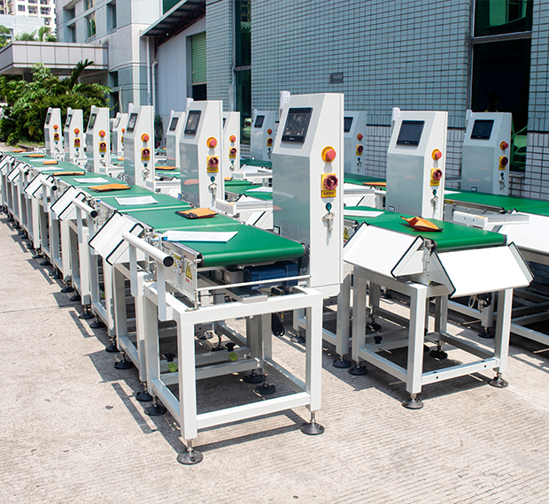 SC3-10060L50 dynamic checkweigher — modular frame, quick-release belt, integrated rejector
Electrical Connection
- Connect supply to the lockable main disconnect; verify voltage matches the nameplate (AC 220 V ±10 %) and the PE conductor is terminated
- Verify PE continuity to the machine frame before first power-on
- Wire motors and sensors per the electrical schematic; seal all cable glands
- Verify drive rotation and jog commands before enabling automatic mode
Pneumatic Connection
- Install the filter–regulator–lubricator (FRL) set at the machine inlet and connect the Φ8 mm air line
- Set the regulator to the working pressure of 0.5–0.8 MPa (0.6 MPa recommended starting point)
- Perform a leak check with soapy water or an ultrasonic detector; pressure must hold steady during a 10-minute observation
- Confirm air quality is dry and oil-free to protect the reject valve block and cylinders
Optional Module Installation
- Mount inkjet coders, printers, labelers, code readers, and sorters per their module drawings
- Connect power and data cables; mount and align encoder/sensor brackets for print trigger and read positions
- Integration-level options (metal-detector combination, DWS systems) follow their dedicated interface drawing
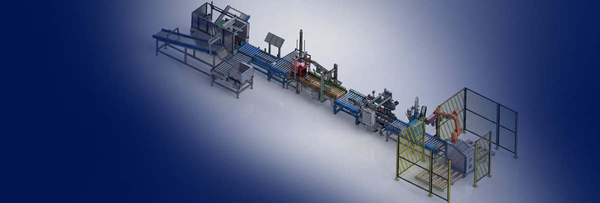
Built and pre-tested in-house
Every machine is assembled, jog-tested, and pre-calibrated on the SameGram production floor before crating — your site work starts from a verified baseline.
Section 3 · Project Sequence
Assembly Workflow at a Glance
A typical full on-site project follows the sequence below. Durations are typical estimates; confirm against your project plan.
| # | Step | Owner | Duration | Exit Criteria |
|---|---|---|---|---|
| 1 | Delivery inspection & unpacking | SameGram + site team | 0.5 day | Packing list verified, damage status documented |
| 2 | Site readiness verification | Site team | 0.5 day | Section 1 checks complete |
| 3 | Positioning & leveling | SameGram engineer | 0.5 day | Level verified; all feet loaded |
| 4 | Mechanical assembly | SameGram engineer | 1 day | Section 2 steps complete |
| 5 | Electrical & pneumatic connection | SameGram + electrician | 0.5 day | Sections 2.3–2.4 complete |
| 6 | Pre-commissioning inspection | SameGram engineer | 0.5 day | Section 4 checklist signed |
| 7 | Calibration & parameter setup | SameGram engineer | 1 day | Section 5 steps 1–6 complete |
| 8 | Integration & communication test | SameGram + IT/reliability | 0.5–1 day | Section 5 steps 7–8 complete |
| 9 | Continuous run & verification | Both parties | 0.5 day | Section 5 step 9 complete |
| 10 | Training & handover | SameGram engineer | 0.5–1 day | Section 7.4 training signed |
Typical total: 3–6 working days
Depending on model, options, and line-integration scope. A remote pre-installation survey can shorten the visit.
Section 4 · Gate Before Power-On
Pre-Commissioning Inspection Checklist
Complete every item before energizing the machine. Do not proceed with any unchecked item.
Mechanical
- Machine leveled; all feet loaded; no rocking
- Transit brackets and shipping bolts removed and retained
- Weighing platform moves freely; no second load path
- Load-cell fasteners torqued per drawing (witness marks applied)
- Belt tracking centered; tension within specification
- Reject unit aligned with reject lane; full stroke unobstructed
- Upstream/downstream transfer heights and gaps verified
Electrical
- Supply voltage verified: AC 220 V ±10 %
- PE conductor connected; continuity to frame verified
- Lockable disconnect installed and labeled upstream of the machine
- Motors and sensors wired per schematic; cable glands sealed
- No tools or debris inside the cabinet
Pneumatic
- Air supply clean, dry, oil-free; FRL installed at inlet
- Working pressure set within 0.5–0.8 MPa
- Leak check passed; pressure holds steady
- Lines secured; no kinks or abrasion points
Data & Communication
- Network cable connected (if equipped)
- USB/export path tested with a sample file
- ERP/MES interface parameters received from the customer (if applicable)
Safety
- All guards installed and fastened
- Emergency stop devices and interlocks complete and untampered
- LOTO points identified and locks available
- Operating area clear; warning signage posted
Documentation
- Installation drawing available on site
- Packing list verified; discrepancies reported
- Model data sheet available for verification values
Section 5 · Bring-Up
Commissioning Procedure
Perform the steps in order. Record every measured value on the commissioning report — these records are the baseline for future verification and warranty support.
 Span calibration with certified test weights at the platform center position
1
Power-on & system start
Confirm Section 4 is complete and personnel are clear of the machine. Close the main disconnect, power on, and verify the HMI boots to the main screen with no fault codes and a working sound-and-light alarm self-check.
2
Zero calibration
Remove all product from the weighing conveyor; clean the platform and belt — residue is the most common cause of zero drift. Jog the belt to confirm free movement. Start Zero Calibration from the HMI (typically 10–20 sampling cycles). Verify zero returns within the model's zero tolerance, typically within ±1 display division.
3
Span calibration with certified test weights
Place a certified test weight at the center of the platform (start at approximately 50 % of capacity) and compare the indicated value against the certificate value — the deviation must fall within the model's stated accuracy at that load. Repeat at a minimum of three load points (approximately 20 % / 50 % / 100 % of capacity). If any deviation exceeds tolerance, perform Span Adjustment in the HMI and re-verify all points. Record certificate numbers and indicated values on the report.
4
Corner (eccentricity) load test
Place the same certified weight at the four platform positions: front-left, front-right, rear-left, rear-right. The spread between the highest and lowest indication must remain within the acceptance-protocol tolerance. An excessive spread indicates a mechanical constraint — re-check the platform for a second load path before adjusting electronically.
5
Dynamic test with actual products
Feed production products (or certified weights as dummies) through the line at production speed. Compare each dynamic indication against a static reference measurement. Acceptance: the mean dynamic error falls within the model's stated dynamic accuracy, and the standard deviation of repeated measurements does not exceed one-third of the reject tolerance band.
6
Product recipe & operating parameters
Enter the target weight and upper/lower reject limits per the quality plan or applicable net-content regulation. Configure batch/lot fields, sampling interval, and the reject confirmation window. Configure alarm behavior (sound-and-light alarm with automatic rejection). Store the configuration as a product formula — the controller stores up to 100 formulas — and verify recall from the product list.
7
Reject function verification
Prepare a seeded test lot: known under-weight and over-weight units mixed into a run of conforming product. Acceptance criteria: 100 % of seeded out-of-tolerance units rejected to the correct destination; zero conforming units mis-rejectedin the test sample; each event correctly logged. Verify the fail-safe: simulate a reject jam or air-pressure loss — the machine must raise an alarm and stop feeding, entering a safe state.
8
Data & traceability test
Export a test-run report (USB or network); every record must contain timestamp, batch/lot, sequence number, measured weight, and verdict. For ERP/MES integration: exchange one full production batch with the customer's system; verify the handshake, field mapping, and zero data loss. Confirm print-label content (batch number, date code, QR code where equipped).
9
Continuous run & parameter backup
Run the machine continuously for at least one hour (or the agreed production quantity) at nominal speed. Monitor zero drift, belt tracking, reject statistics, and the alarm log. Back up all recipes and calibration parameters to USB; the backup accompanies the documentation at handover.
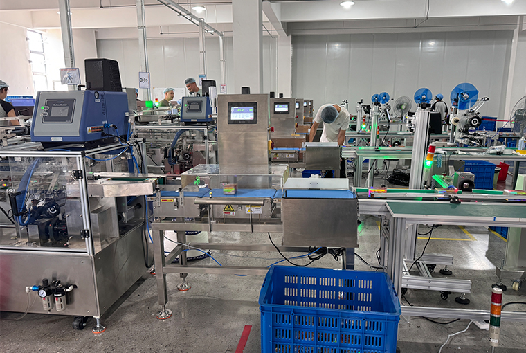 Installed SameGram checkweigher running on a customer production line
Section 6 · Non-Negotiable
Safety Specifications
The machine contains moving parts, pneumatic actuators, and circuits operating at mains voltage. The rules below apply in addition to local regulations and site procedures.
Qualification notice
Installation, commissioning, and service work must be performed only by qualified personnel who have read the operator manual. No modification, bypass, or defeat of safety devices, guards, or interlocks; no service or cleaning while the machine is energized or pressurized; untrained personnel must remain outside the marked operating area during operation.
Mechanical Safety
- Pinch and crush points exist at the reject unit, lifting mechanisms, and belt transfer points — never operate with guards removed
- Never reach into, ride on, or step on the conveyor while powered
- Lockout/Tagout (LOTO)before any mechanical intervention: isolate power and air, dissipate stored energy, apply personal locks, verify zero energy
Electrical Safety
- Only qualified electricians may open the control cabinet; disconnect at the lockable main switch and verify absence of voltage first
- Protective earth must be connected and verified before the first power-on
- Do not work on live circuits; use insulated tools
Pneumatic Safety
- Depressurize and lock out the air supply before servicing reject actuators or valve blocks
- Never direct compressed air at people — ejected parts can cause injury
Emergency Stop & Interlocks
- Test all emergency stop devices and guard interlocks at every power-on
- Do not use the E-stop as a routine stop button; investigate and correct the cause of every E-stop event
Hygiene & Food-Contact Safety
- For food and pharmaceutical applications, use the washdown-duty (IP-rated) variant where required
- Use cleaning agents compatible with stainless components and the food-grade belt; rinse and dry after cleaning
- After cleaning, re-verify zero stability before restarting production
Personal Protective Equipment
| Machine handling & lifting | Safety shoes, cut-resistant gloves, high-visibility vest |
| Electrical work | Insulated gloves, eye protection — qualified electrician only |
| Pneumatic work | Eye protection |
| Cleaning (food/pharma) | Chemical-resistant gloves and apron per the cleaning agent SDS |
Section 7 · Sign-Off
Acceptance Criteria
Acceptance is recorded jointly by the customer and the SameGram engineer. The criteria below apply to all commissioning service models.
| Test | Method | Typical Acceptance Criterion |
|---|---|---|
| Zero stability | Empty-belt zero cycle | Zero returns within ±1 display division |
| Static accuracy | Certified test weights at ≥3 load points | Indicated value within data-sheet accuracy at each point |
| Eccentricity (corner) error | Certified weight at 4 platform positions | Spread within the acceptance-protocol tolerance |
| Dynamic error | Seeded run at production speed | Mean error within stated dynamic accuracy |
| Repeatability | ≥20 consecutive runs of the same unit | Standard deviation ≤ one-third of the reject tolerance band |
| Reject accuracy | Seeded defect lot | 100 % of out-of-tolerance units correctly rejected |
Functional Acceptance
- All ordered options verified: real-time printing, inkjet coding, online code reading, labeling, sorting, and metal-detector combination where equipped
- Recipe save/recall verified for each configured product
- Sound-and-light alarm and automatic rejection verified
- Reject-bin monitoring / jam alarm verified where equipped
Documentation Handover
- Installation & commissioning report (with recorded values from Section 5)
- Calibration record with test-weight certificate numbers
- As-built layout drawing (updated with any site changes)
- Parameter backup (USB / digital copy)
- Operator and maintenance manual
| Final Sign-Off Milestone | Customer Representative | SameGram Engineer | Date |
|---|---|---|---|
| Mechanical installation complete | ☐ | ☐ | |
| Calibration & metrological verification | ☐ | ☐ | |
| Reject & data functions verified | ☐ | ☐ | |
| Training completed | ☐ | ☐ | |
| Final acceptance & handover | ☐ | ☐ |
Training covers operator duties (daily operation, recipe selection, cleaning routine, alarm response) and maintainer duties (belt replacement and tensioning, load-cell precautions, common troubleshooting), recorded with an attendance sheet signed by the trainees.
Engineer Q&A
Frequently Asked Questions
How long does installation and commissioning take?
Typical on-site duration is 3–6 working days, depending on the model, ordered options, and line-integration scope. A remote pre-installation survey can shorten the visit.
Can SameGram commission a checkweigher on our existing production line?
Yes. We survey upstream and downstream interfaces, conveyor heights, and controls in advance, and issue an integration drawing before the machine ships, so the drop-in fit is verified on paper first.
What test equipment do we need to provide on site?
Certified test weights covering approximately 20 %–100 % of the machine's weighing capacity. SameGram engineers bring all specialized field tools.
What documentation do we receive at handover?
A commissioning report, calibration records, parameter backups, an as-built layout drawing, and a signed acceptance certificate.
Is remote commissioning support available?
Yes. Video guidance and documented self-installation support are available, and remote sessions parameter-check existing installations in service. On-site commissioning is recommended wherever line integration is involved. See Remote Support.
Which regions do you install and support in?
SameGram installs and services equipment internationally, including Southeast Asia, Europe, and the Middle East, with spare-parts logistics and remote support for overseas plants. See Repair Services & Spare Parts.
Ready to schedule your installation?
Our service team will confirm the site inspection checklist and prepare your integration drawings before the machine is shipped.

- Product Finder
Quickly filter to find the product you want

- Inventory Machines
Short delivery time and quick installation

- Free Test Piece
Confirm after sensitivity test

- Customization Support
Inspiring customized solutions